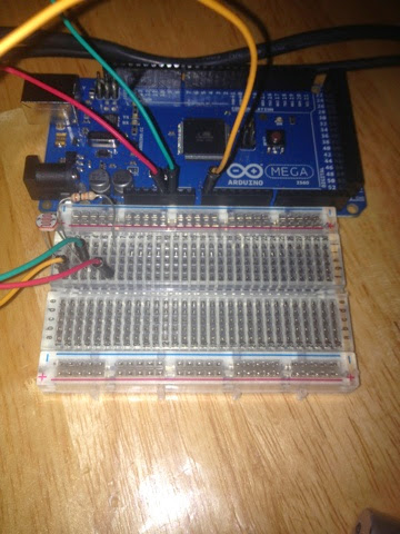
The circuit is very simple. A photoresistor, a 10K resistor and a laser pointer.
I used this link to provide the basis for the wiring – as I said it’s a very simple circuit.
http://nakkaya.com/2009/10/29/connecting-a-photoresistor-to-an-arduino/
When hit with the laser directly, the photoresistor registers in the 20s. When the beam is broken the photoresistor registers somewhere above 600s.
Since the idea is that the alarm sounds when the laser is broken, we can give a little wiggle room (so to speak).
I did modify the code slightly from the above post.
As this code stands, if it were deployed, my son would have to unplug and plug back in the arduino (or hit the reset button. I could add a “reset” button that basically sets the alarm back to ok. If I wanted to get even fancier I could add an LCD and a keypad so he’d have to follow instructions on the keypad to reset the alarm (or any kind of RFID or an IR transmit and receive) – really any kind of way to reset the panel.
 int lightPin = 0; //define a pin for Photo resistor
 int threshold = 250;
 void setup(){
   Serial.begin(9600); //Begin serial communcation
   pinMode(13, OUTPUT);
 }
 void loop(){
   int readPin = analogRead(lightPin);
   Serial.println(readPin);
   if (readPin > 0 && readPin < 100) {
   } else {
     Serial.println("ALLLAAAAAAAAAAARRRRMMMM");
   }
   delay(100);
 }