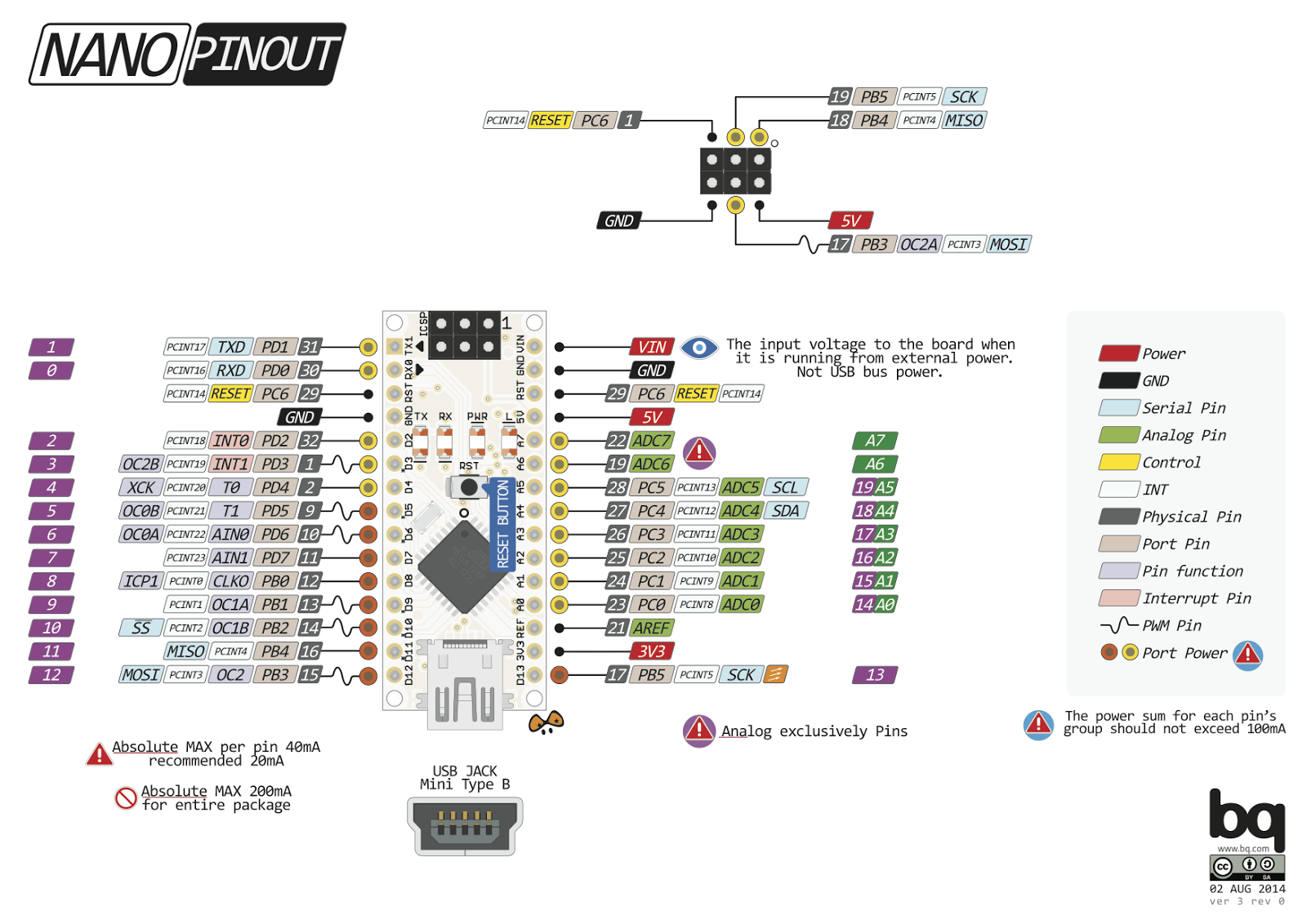
I took to the Arduino Nano schematic so I could figure out which pins are which.
http://arduino.cc/en/uploads/Main/ArduinoNano30Schematic.pdf
I don’t remember where I found this PNG (one of the Aruino forum posts), but here’s a nice detailed image of the Nano.
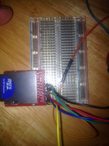
Alright, with all of that, let’s wire this up and get to the code (which will be a very fast tutorial).
Fortunately for us this build follows the pin recommendations that are inside the Datalogger sketch save one: CS – pin 4 should be 10
Remember this from the last post:
CS – Chip Select
D1 – MOSI
VCC – 3.3v
CLK – Clock
GND – Ground
D0 – MISO
CS goes to pin 10 (D10)
D1 – MOSI – to pin 11 (D11)
D0 – MISO – to pin 12 (D12)
CLK – to pin 13 (D13 – opposite side of the board from D12)
when you’re done go into the Datalogger sketch and change one line:const int chipSelect = 4; to const int chipSelect = 10;
then compile and upload. Fire up the serial monitor when you’re done and watch the numbers scroll like they did on the Mega.
Now it’s time to wire up the bluetooth HC-05 and OLED, load data from the SD card and then display it on the OLED.