The first thing I did was follow the two Arduino tutorials on the LCD and the PING))) and hook them up to a solderless breadboard.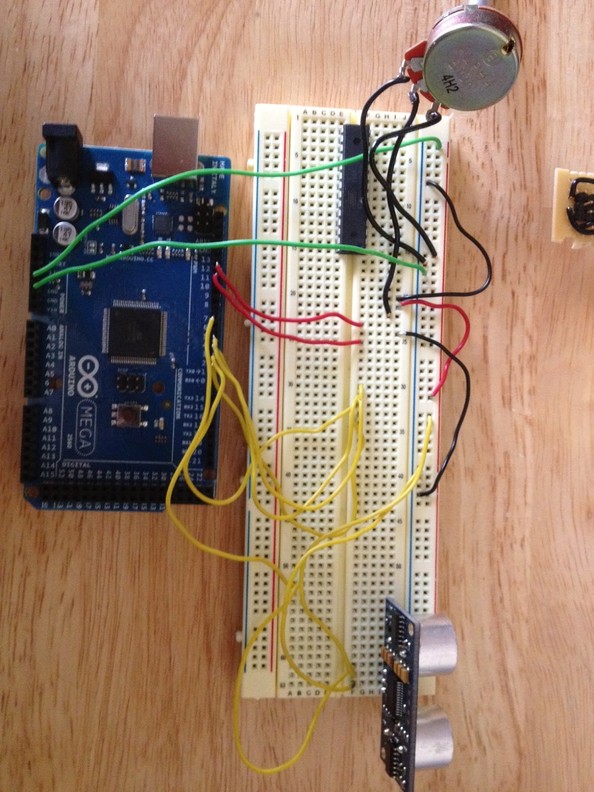
I then copied the PING code to the LCD code and saved them as a new file. In the photo above you can see the ATmega328p that we will be interfacing with for the second project.
I’ve included all of the code below and go through an explanation below that.
// include the library code:
#include

// initialize the library with the numbers of the interface pins
LiquidCrystal lcd(12, 11, 5, 4, 3, 2);

// this constant won't change.  It's the pin number
// of the sensor's output: for the PING)))
const int pingPin = 7;

void setup() {
  // set up the LCD's number of columns and rows:
  lcd.begin(16,2);

  // initialize serial communication:
  Serial.begin(9600);
}

void loop() {
  long inches = pingLoop();
  lcdLoop(inches);
}

void lcdLoop(long inches) {
// set the cursor to (0,0):
  lcd.setCursor(0, 0);
  lcd.clear();

  String output = "";
  output += inches;
  lcd.print(output);
}


long pingLoop() {
  // establish variables for duration of the ping,
  // and the distance result in inches and centimeters:
  long duration, inches, cm;

  // The PING))) is triggered by a HIGH pulse of 2 or more microseconds.
  // Give a short LOW pulse beforehand to ensure a clean HIGH pulse:
  pinMode(pingPin, OUTPUT);
  digitalWrite(pingPin, LOW);
  delayMicroseconds(2);
  digitalWrite(pingPin, HIGH);
  delayMicroseconds(5);
  digitalWrite(pingPin, LOW);

  // The same pin is used to read the signal from the PING))): a HIGH
  // pulse whose duration is the time (in microseconds) from the sending
  // of the ping to the reception of its echo off of an object.
  pinMode(pingPin, INPUT);
  duration = pulseIn(pingPin, HIGH);

  // convert the time into a distance
  inches = microsecondsToInches(duration);
  cm = microsecondsToCentimeters(duration);

  delay(100);

  return inches;
}

long microsecondsToInches(long microseconds) {
  // According to Parallax's datasheet for the PING))), there are
  // 73.746 microseconds per inch (i.e. sound travels at 1130 feet per
  // second).  This gives the distance travelled by the ping, outbound
  // and return, so we divide by 2 to get the distance of the obstacle.
  // See: http://www.parallax.com/dl/docs/prod/acc/28015-PING-v1.3.pdf
  return microseconds / 74 / 2;
}

long microsecondsToCentimeters(long microseconds) {
  // The speed of sound is 340 m/s or 29 microseconds per centimeter.
  // The ping travels out and back, so to find the distance of the
  // object we take half of the distance travelled.
  return microseconds / 29 / 2;
}
I left a lot of code from the PING project — the microsecondsToInches, microsecondsToCentimeters and the loop (which I renamed the pingLoop). You’ll also notice I renamed the loop to the pingLoop and it returns a long. What I wanted to do here was get the value and then use it later (which we see in the loop() method);
In the lcdLoop(), which is mostly the loop from the Arduino LCD project, I have added the long inches parameter so that we can use that value to display on the LCD. In this loop, we clear the LCD, then display the parameter to the LCD.
You can see in this (blurry) picture the shorter solderless breadboard I moved the components to and wired them to the Arduino Mega 2560.

In this photo you can see that I’ve folded the Arduino behind the solderless breadboard (the perfect size to fit behind the Arduino – especially with the foam pad behind it.) 
Here is a shot of the Arduino/LCD/Ping from the side showing how I’ve folded it over
This was a very simple project to do. I’ll head out later to get some parts to build the 9V Battery Adapter so I can build a prototype box for the Arduino and the ping, etc with the battery to make a cool enclosure to house them while we play.
The very next thing after that is hooking up the components to the ATmega328p or maybe one of my ATTiny84 (I think there are enough pins on it to do the next portion of the project.)
